Lab Software Development 3 - Scanning Probe Microscope Controller
Motivation
For home-build scanning probe systems in labs, SpecsGroup's Nanonis system is often considered a good solution with various working modes for piezo stage control. However, its' price may not be very friendly for some SPM systems, which do not need a sophisticated feedback PID loop. It is overkill especially for the non-feedback laser microwave impedance microscopy system in our lab. We had a LabView program developed by former students, but it lacks the rotational degree of freedom and line scan mode. Also, the UI's inconvenience has always been painful for users. In order to add more flexibility, I rebuilt a new control system for the SPM with QtCreator with Python as the backend.
Functionalities
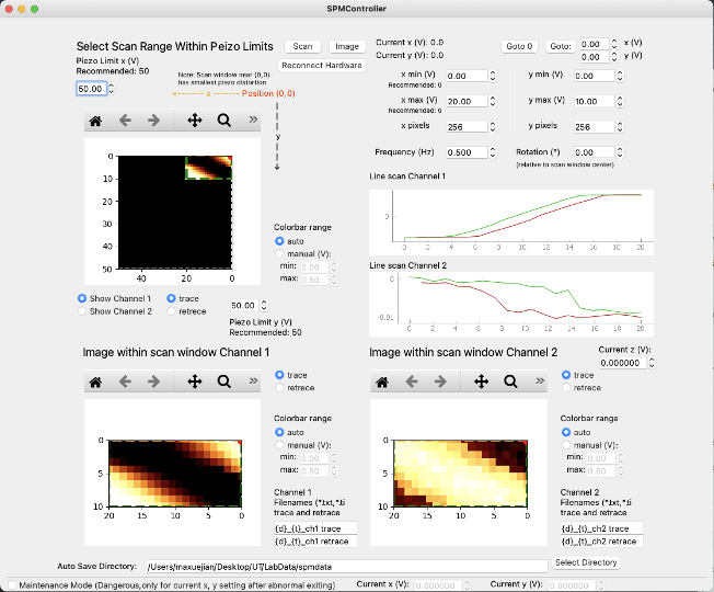
For convenience, all functionalities are embedded on the same page. Multithreading was implemented for scanning, imaging, and data saving. Many of the functionalities are following the workflow of Park AFM system.
Scan: By clicking "Scan", the controller will first move the tip to the starting point with the speed calculated from the frequency provided by the user. Then the program will continuously scan the starting line and show the linecuts of trace and retrace in real-time. After clicking it, the button will become a button with text "OFF" and all parameter boxes will be greyed out for safety. By clicking "OFF", the scan will halt immediately.
Image: This is the core functionality of the controller. After hitting the "Image" button, the scanner will start to run line by line with given parameters. The box on the top-left graph window shows the scanning window relative to the whole reachable regions of the piezo as the black background suggests. Tuning the parameters of x, y, and rotation will shift the scan window accordingly for imaging. When the parameters makes the window out of the piezo limit, there will be an error popping out, the box in the graph will turn red, and the scan/image button won't work before the error is resolved by adjusting the scan window. The top-left graph is intended for finding the good scan window, while the bottom two graphs are zoomed-in images from two channels of our signal inputs: channel 1 and channel2, corresponding to MIM imaginary and real parts. Of course one can use the two channels for other purposes other than MIM measurement.

Signal I/O: The official NI DAQ API was used in data input and output and the data will be displayed in real-time in the line scan graphs. Since users may use large frequencies, the real-time display may lag due to the high refreshing rate. Here I implemented batch processing with a 100ms time interval to avoid possible freezing. Also, since the DAQ API signal reading takes a significant amount of time and the time may vary for each pixel, I make the waiting time for each data point dynamic and it can be adjusted automatically to make the whole scan smoothly.
File saving: The files will be saved in the given directory with the given filename. Users can use {d} and {t} to replace the current date and time in filename. File saving usually takes some time. Since we want to save data every time a line is finished, a different thread was implemented for file saving to avoid the imaging module from freezing. Files will be saved in two formats. "*.txt" file contains the raw data, and ".tiff" file has XEI-readable data format.
Image parameters: Users can freely choose Channel 1/2 and Trace/Retrace. The UI will update the corresponding graphs instantly.
Z-control and maintenance mode: Z-controller is also included for quick MIM tip approaching or reapproaching. The maintenance mode is optional for users to deal with emergent situations such as loss of status due to a computer or program crash.
Auto Approach: The z-scanner can be automatically controlled and adjusted for probe (tip) approach process. Feedback comes from Lock-in demodulated AC-MIM signal. The approach panel supports all click-based turning ON/OFF for DC and AC peizo controls.

Laser Control System: This tab controls three hardware - OPA laser controller, ND filter controller, and power meter. OPA can sweep wavelength, but may yield different powers. To keep the laser power constant, there's a calibration module to simultaneously adjust wavelength and ND filter. With gradient descent method, the ultimate power should remain constant with proper ND filter angles for each wavelength. With the calibration, one can take measurement for photoconductivity when sweeping the wavelength.
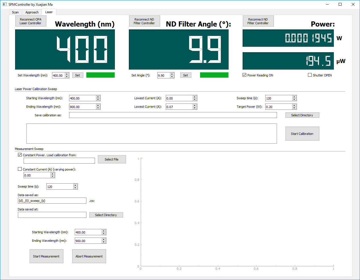
The hardware module is independent from the SPM controller main module. Users can easily create their own hardware I/O module with their own devices while using the same interface.
Project Link: https://github.com/xuejianma/spmcontroller
Min deposit $10 or more using the deposit code 100CASINO. Although we offered our high ideas 점보카지노 above, tons of|there are numerous} different on-line casinos to choose from|to choose from} in Pennsylvania. Here's the record, along with each on line casino's land-based partner, if you want to|if you wish to} explore your whole vary of options.
ReplyDelete